MEMS, formally the acronym of Micro Electro Mechanical Systems, is the term born in the USA to indicate a family of devices made up of mechanical structures and electronic circuits integrated on the same silicon chip. An emerging field of MEMS applications, known as RF MEMS, is that of radio frequency and millimeter wave systems. Devices such as micro switches, tunable capacitors, high-Q inductors, micro-machined antennas, micro transmission lines and micro-mechanical resonators have been proposed and some of them are now commercially available.
In this field, the Section of Pisa has been designed micromechanical resonators with frequency in the range 10¸50 MHz and an estimated quality factor Q of some thousands. These devices can be used as filters or to perform both frequency translation and filtering.
Two different topologies of resonators have been designed: (i) clamped-clamped beams and (ii) free-free beams.
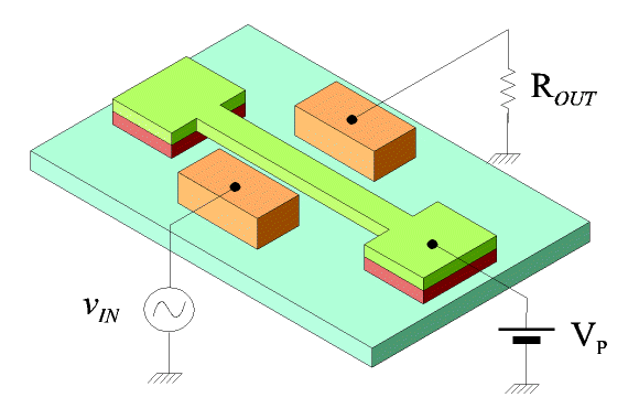
In Fig.1 a schematic view of the clamped-clamped beam in a dual port configuration is shown: the beam is electrostatically driven by one electrode and the motion is detected by using the capacitance variation between the beam and the other electrode. To vibrate, an AC drive voltage vIN is applied to the electrode and the resulting beam motion is detected as current flowing in the output resistor ROUT. When the microstructure is driven at its resonance frequency, its motion and the output current reach their maximum amplitude. The DC voltage VP serves two purposes: (i) avoiding that the microstructure moves at twice the frequency of the applied drive voltage and (ii) amplifying the output device current due to the beam motion.
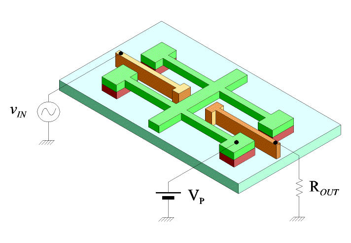
Clamped-clamped beams are characterized by low Q values due to the dissipation at the anchor points. High-Q resonators are based on a free-free configuration. In Fig. 2 a schematic view of the free-free beam resonator is shown. In this case, the central vibrating beam is not directly anchored to the substrate thus eliminating any dissipation effect. The four support beams must be strategically designed in order to isolate the central beam from the anchor effects.
In the design of the resonators, two typical issues have been faced: (i) high insertion loss values and (ii) low resonance frequencies. An electrostatic actuator has been introduced with the aim of reducing the gap between the beam and the electrodes and thus obtaining a minor insertion loss. As far as the resonance frequency value is concerned, a more complex electrodes layout has been designed in order to stimulate the third order vibration mode.
In Fig.3 the layout of a designed resonator is shown. The chip has been fabricated using a STMicroelectronics process thanks to the agreements with both "Information Engineering Department: Electronics, Computer Engineering and Telecommunications" of the University of Pisa and the Section of Pisa of the IEIIT which is located in that Department.
Vedi anche:
Immagini:


